Contact plans are a critical part of any space mission, therefore any space link and network. A contact plan defines how and when contacts (i.e. a communication event) can be established between two or more elements.
Why is this critical? Due to celestial mechanics, infrastructure sharing and power constraints in space assets, it is impossible to establish continuous links between two planets (with some exceptions). Basically, deploying a fiber optic cable or a point to point optical or microwave link with 24x7 connectivity is in general not possible. These links work only sporadically (e.g. when the two elements in orbit, or planet surface are in line of sight), and these times in which two points can establish communications are called contacts. Then, contact plans become a critical planning and execution mechanism by which mission operations ensure the delivery of commands, and navigation and telemetry data.
Delay Tolerant Networking includes contact plans in its routing layer as a way to optimize the routing decisions. As such each DTN node is aware of the network contact plan around at any given time.
This article reviews contact plans in DTN literature, describing the fundamentals and performs a high level exploration of contact plan management in existing DTN implementations.
Introduction to DTN Contact Plans
According to CCSDS 734.3-B-1 Schedule-Aware Bundle routing contacts plans are critical to use in networks in which changes in connectivity are planned and scheduled, rather than predicted, discovered or contemporaneously asserted. This considers:
- Episodes of communication between robotic spacecraft in interplanetary space and ground stations on Earth are typically scheduled weeks or months before they occur.
- The beginning and end of each communication opportunity between an orbiting spacecraft and a communication asset on a planetary surface, can be computed from known orbital elements.
- Power-conserving assets may communicate on infrequent, fixed intervals established by network configuration.
The CCSDS Recommended Standard specifies the contents and handling of DTN contact plans for space. The basic strategy of schedule-aware bundle routing (CCSDS term) is to take advantage of the fact that the communication routes between any pair of bundle protocol agents in a population of DTN nodes that have all been informed of one another's plans can be inferred from those plans rather than discovered via dialogue, which is impractical over long distances. This information takes the form of contact plans.
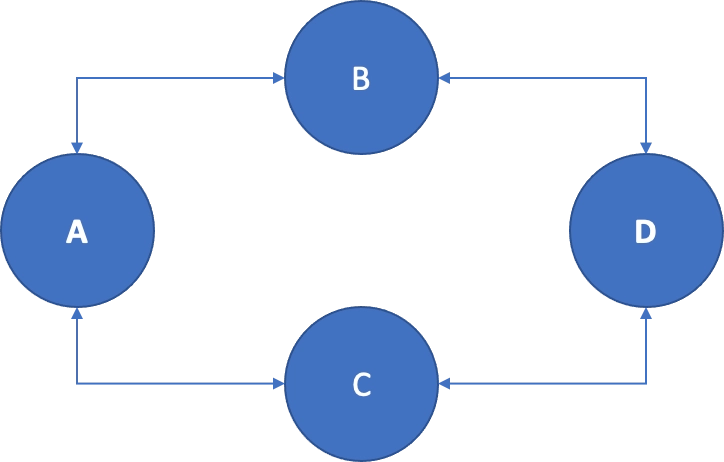
Figure. Network Topology Example. From CCSDS 734.3-B-1.
A contact is defined as an interval during which it is expected that data will be transmitted by DTN node A (sending node) and most or all of the transmitted data will be received by Node B (contact receiving node). The sending node will utilize some convergence layer protocol below the Bundle Protocol (BP).
- its start time,
- its end time,
- the identities of the sending and receiving nodes, and
- the mean rate at which data are expected to be transmitted by the sending node throughout the indicated time period.
The duration of the contact is given by subtracting the contact's start time from its end time. The volume of the contact is the product of its duration and its expected mean data transmission rate.
Note a contact is not an episode of activity on a link. Episodes of activity on different links may well overlap, but contact by definition cannot, they are bounded by time intervals and as such are innately tiled.
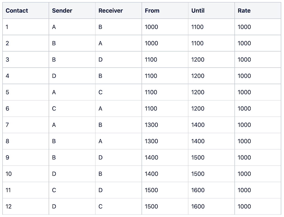
Table. Contact Plan Example: Contacts. From CCSDS 734.3-B-1.
A range interval is a period of time during which the displacement between two nodes A and B is expected to vary by less than one light second from a stated anticipated distance.
A range interval is characterized by- its start time,
- its end time,
- the identities of the two nodes to which it pertains, and
- the approximate distance between those nodes throughout the indicated time period, to the nearest light second.
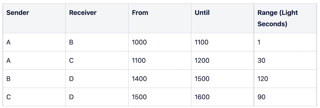
Table. Contact Plan Example: Range Intervals. From CCSDS 734.3-B-1.
The contact plan is used to generate the node forwarding (route) table. Currently, the main algorithm used to generate the forwarding table from the contact plan is the Contact Graph Routing (CGR)method. There are other supplementary routing procedures, some of which are specified as alternative route determination procedures and include routing to neighbor, static routing, routing (determination) failure, and others that are described in a little more detail in the CCSDS Recommended Standard mentioned above.
Existing Contact Plan implementations
Note the information below is a summary and does not include all the configuration capabilities. Please refer to each implementation manual for complete details.
NASA/JPL Interplanetary Overlay Network (ION)
ION is considered the most complete DTN implementation for space and has a relatively advanced contact plan implementation, it is capable of using CGR routing.
In ION, the contact plan is stored in text form in the ionadmin process.
The following is the format to add a contact in ION:
a contact start_time stop_time source_node dest_node xmit_data_rate [confidence]
start_time: It is the start time of the contact. In ionadmin, time is either absolute or relative, it might be an absolute UTC day-time or relative to the internal clock reference.
stop_time: It is the stop time of the contact.
source_node: EID of the source node. e.g. 1
dest_node: EID of the destination node. e.g. 2
xmit_data_rate: Rate of data transmission in BYTE/SEC.
[confidence]: Defaults to 1.0, which is the value when a contact is scheduled. It indicates an estimation of the likehood of the potential contact.
Example of a contact in ION:
a contact +60 +7260 1 2 10000
schedules a period of transmission at 10,000
bytes/second
from node 1 to node 2, starting 60 seconds after
the reference time and ending exactly two hours (7200 seconds) after it starts.
ION also allows for changing, deleting and listing and printing existing contacts:
c contact start_time source_node dest_node xmit_data_rate [confidence]
changes the data transmission rate and possibly the level of confidence in the scheduled period of
data
transmission from source_node to dest_node starting at start_time.
d contact start_time source_node dest_node
deletes the scheduled period of data transmission from source_node to dest_node
starting
at
start_time.
i contact start_time source_node dest_node
prints information (stop time, data rate, confidence) about the scheduled period of transmission
from
source_node to dest_node that starts at start_time.
l contact
lists all scheduled periods of data transmission.
The following is the format for adding a
range:a range start_time stop_time one_node the_other_node distance
start_time: It is the start time of the contact. Note the time might be an absolute UTC day-time or relative to the internal clock reference.
stop_time: It is the stop time of the contact.
one_node: EID of the first node. e.g. 1
the_other_node: EID of the destination node. e.g. 2
distance: Distance in light seconds.
Example of a Range in ION:a range +1 2009/01/01-00:00:00 1 2 12
predicts that
the
distance between nodes 1 and 2 (endpoint IDs ipn:1.0 and ipn:2.0) will remain constant at
12 light seconds over the interval that begins 1 second after the reference time and ends at the
start
of
calendar year 2009.
Note: The ranges declared by these commands are directional. ION does not automatically assume that the distance from node A to node B is the same as the distance from node B to node A. While this symmetry is certainly true of geographic distance, the range that concerns ION is the latency in propagating a signal from one node to the other; this latency may be different in different directions because (for example) the signal from B to A might need to be forwarded along a different convergence-layer network path from the one used for the signal from A to B. As a convenience, ION interprets a range command in which the node number of the first cited node is numerically less than that of the second cited node as implicitly declaring the same distance in the reverse direction unless a second range command is present that cites the same two nodes in the opposite order, which overrides the implicit declaration. Note that ranges should never overlap.
Similar to the contact case, ION also allows for deleting and listing and printing existing ranges.
Note no change command for range in the ION logic. This is to keep the range calculations simple given the rules that govern ranges (no overlap, cascading operations).
Note that due to the advanced features in ION, such as multi-region, streaming and multicast, there are multiple concepts of higher level abstractions that may be part of the configuration beyond a basic contact plan. One of these concept is the concept of region, that includes variations in terms of additional commands that might be needed to properly setup the forwarding plan. This is currently out of the scope of basic interoperability given ION is the only implementation supporting it, however it is important to understand how it works.
µD3TN implementation
µD3TN is a reference commercial implementation developed by D3TN GmBH which has been tested in space and was originally developed for embedded low computing assets.
In µD3TN (read micro DTN), configuration can be performed by sending bundles to the <µD3TN_EID>/config endpoint.
The following is the command format:
<COMMAND>
This command format is used to add connected nodes as well as (upcoming) contacts.
<COMMAND>: Command can have any of three values:
1, adding the node if it does not exist, and assigns the associated endpoints and contacts to it.
2, Replace. Deleting the node if it exists already, then recreate it with the provided data.
3, Delete the given endpoints or contacts from the given node, or delete the node altogether if no endpoints or contacts are provided.
<NODE_ID_STRING>: Node ID, mandatory. All strings shall be enclosed in parenthesis, e.g.(dtn://ud3tn2.dtn) is a valid Node ID.
<,RELIABILITY>: Optional. It is a number between 100 and 1000, and represents the expected likelihood that a future contact with the given node will be observed, divided by 1000.0.
<:CLA_ADDRESS_STRING>: Mandatory when creating a node, and consists of the convergence layer adapter and the node address, e.g., (tcpclv3:127.0.0.1:1234). Notation is similar to Node_ID_STRING.
<:REACHABLE_EID_LIST>: Optional. It shall be enclosed in squared brackets and contain comma-separated EIDs in the same representation as the Node_ID_STRING. e.g. [(dtn://18471),(dtn://81491)].
<:CONTACT_LIST>: Optional. It contains comma-separated contacts in the following format:
{<START_DTN_TIME>,<END_DTN_TIME>,<DATA_RATE>,<REACHABLE_EID_LIST>}
The START_DTN_TIME and END_DTN_TIME shall be integer DTN timestamps in seconds, using Unix timestamp. The DATA_RATE shall be an integer number representing the expected transmission rate in bytes per second. The REACHABLE_EID_LIST uses the same format as the one for the node and is appended only for the specific contact.
Following are examples of configuration data including contact plan information:
1(dtn://ud3tn2.dtn):(mtcp:127.0.0.1:4223)::[{1401519306972,1401519316972,1200,[(dtn://89326),(dtn://12349)]},{1401519506972,1401519516972,1200,[(dtn://89326),(dtn://12349)]}]
1(dtn://ud3tn2.dtn)::[(dtn://18471),(dtn://81491)]:[{1401519406972,1401819306972,1200}];;
The µD3TN Application Agent Protocol (AAP) can also be used to configure contacts. In this case the syntax is simplified thanks to the utilities provided. For example, the code below creates a contact between node A (dtn://a.dtn) and B (dtn://b.dtn) via a tcp convergence layer. Both nodes residing on the same machine (localhost).
python tools/aap/aap_config.py --tcp localhost 4242 --dest_eid dtn://a.dtn --schedule 1 3600 100000 dtn://b.dtn mtcp:localhost:4225
Contact Plan - Less implementations
There are other DTN implementations for space where contact plans are more logically separated from the DTN (or “BP” engine). These implementations have focused on the core of the DTN technology (i.e. the Bundle Protocol) and leave out other functions (such as routing and contact plan management) to other functions.
One of these implementations is the European Space Agency (ESA) Java DTN. Instead of integrating contact plans, it uses mapping between sets of destination EIDs to CL adapters which can be changed dynamically during runtime (based e.g. on an opportunistic event or by a routing algorithm), giving the implementation flexibility as of how to support contacts and routing in multiple scenarios.
NASA HDTN (High-rate Delay Tolerant Network) does not offer its own implementation for contact plan management, however it is able to integrate with contact plan management (and routing) functions such as pyCGR, an implementation of CGR built by Juan Andres Fraire.
Header image: An example of an interplanetary network with the Moon and Mars, property of NASA.